Infrared Line Tracker follower Sensor Module 3 in 1 – TCRT5000
2.95 د.ك
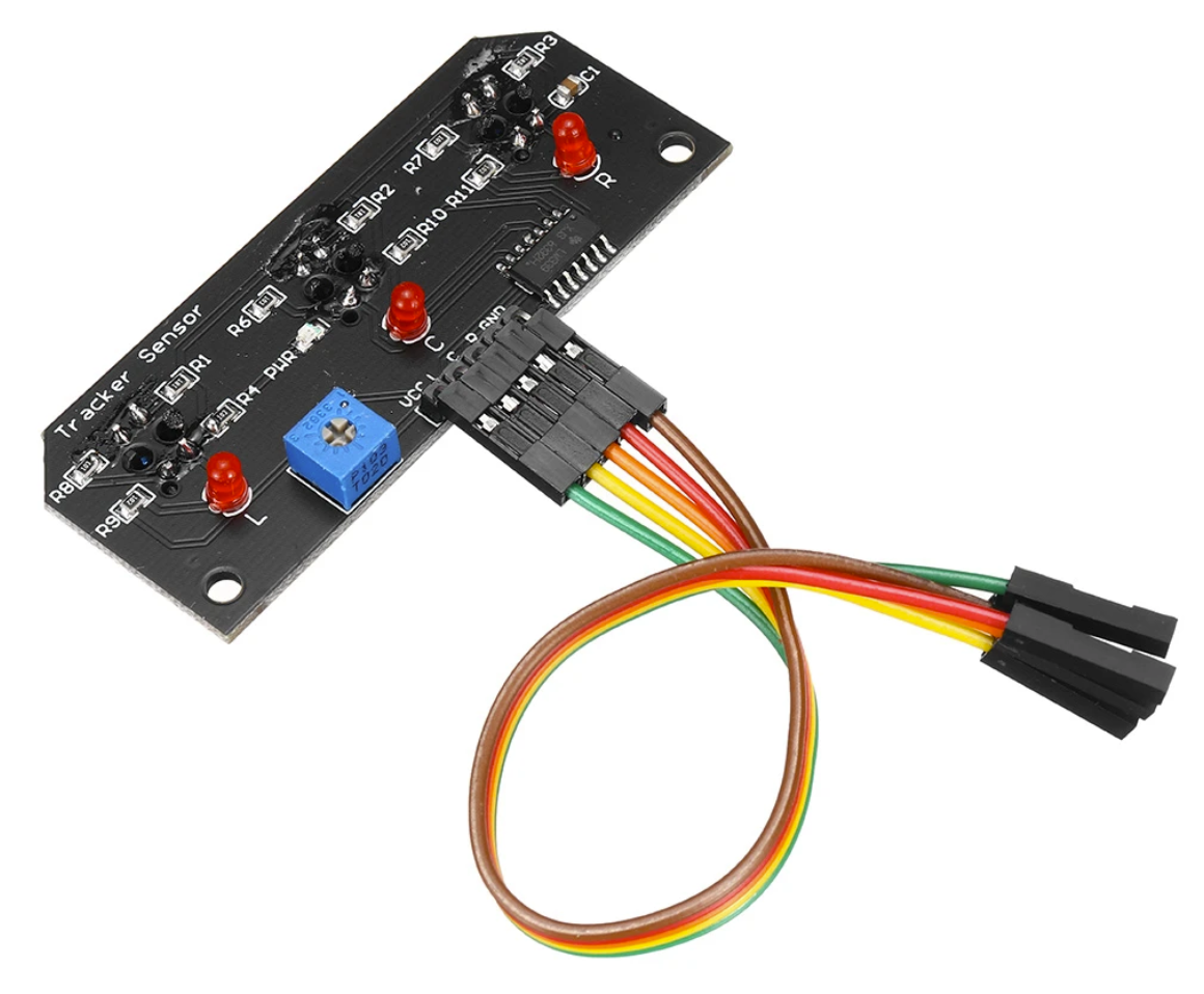
The 3 Channel Line Tracking Module is used on robotic vehicles to allow them to optically follow a line on the floor. Line tracking is one of the easiest ways to implement navigation by a robotic vehicle.
In stock
Description
The 3 Channel Line Tracking Module is used on robotic vehicles to allow them to optically follow a line on the floor. Line tracking is one of the easiest ways to implement navigation by a robotic vehicle.
Package Includes:
- 3 Channel Line Tracking Module
- 5x Jumper Female to Female
Key Features of 3 Channel Line Tracking Module:
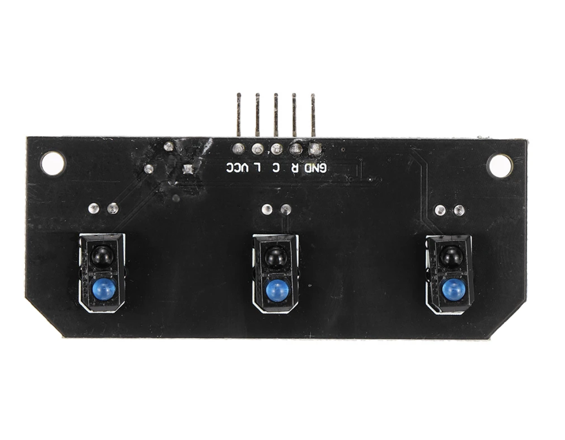
- 3 sets of IR Transmitter / Receiver pairs
- Sensitivity control
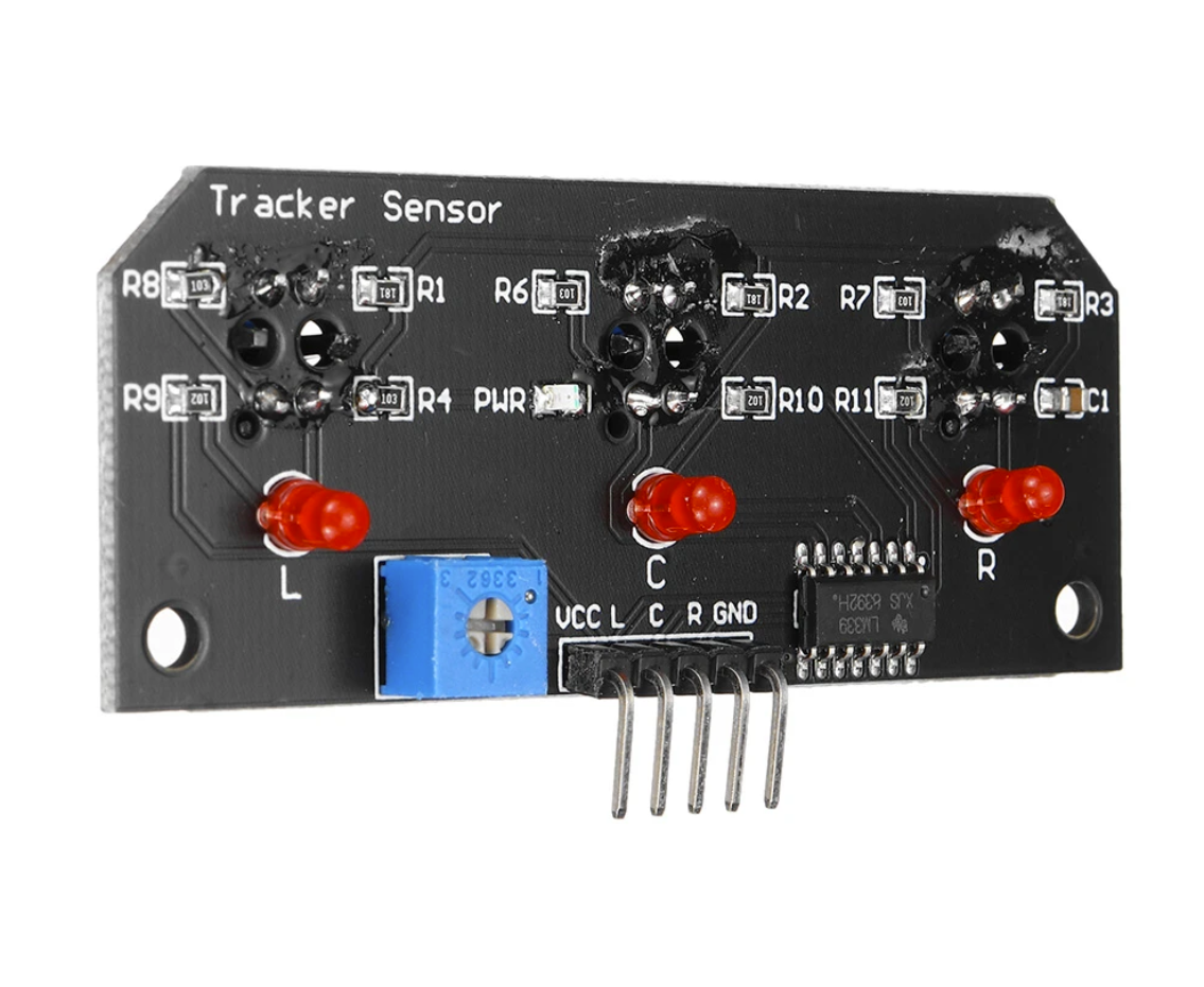
- Detection of active LED indicators
Line tracking works by detecting a difference in the amount of reflection between the line you are trying to follow and the adjacent surface of the floor. The line can either be more or less reflective than the surrounding surface, what is important is that there is a difference that can be detected. This might be shiny white tape placed over a carpeted area or narrow shiny white tape placed on a wide flat black tape. It could also be flat black tape placed on a shiny floor. The software logic will need to know whether you are trying to follow a reflective or non-reflective line.
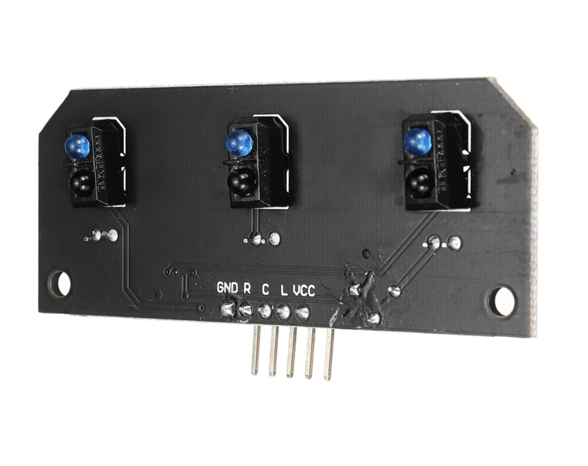
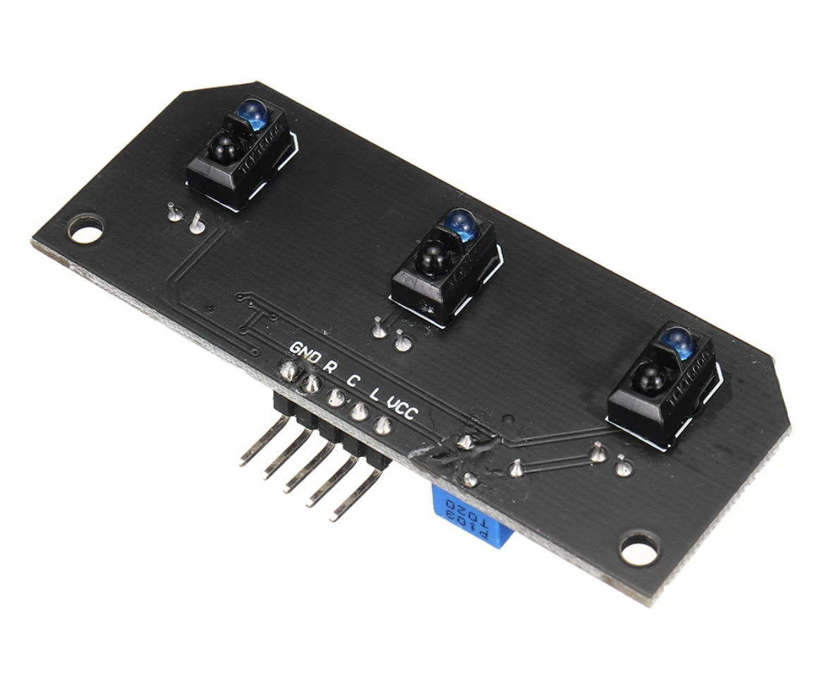
The detection works by emitting an infrared (IR)beam downward and sensing if the IR is being reflected off a reflective surface or not to determine if the sensor is positioned over the line. If you are not over the line, then to know if you are to the left or right of the line, you need at least 2 more sensors, with one positioned on either side of the center sensor.
This Line Tracking module utilizes 3 IR transmitter/receiver pairs spaced about 25mm (1″) apart to implement a complete line tracking setup.
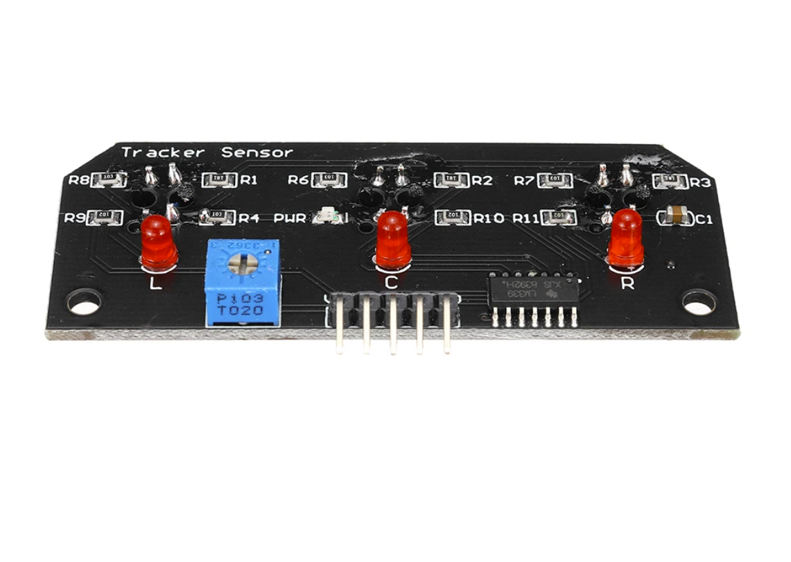
The module is very straightforward to use. 5V power and ground are applied to the module and a green LED light to show power is applied. The module provides 3 logic-level outputs, one each for the left, center, and right sensor assemblies (channels). These outputs are normally at a logic HIGH level. When a sensor detects an IR reflection from its associated transmitter, the output for that channel goes LOW and the associated red LED on the back of the board lights.
In operation, the assembly is typically mounted low on the front of the vehicle with the IR transmitter/receiver pairs facing down. If the vehicle is following a reflective stripe (such as white tape on a carpet or dark floor), normally the center channel will be active if the vehicle is centered over the stripe. If the center channel goes inactive and the left channel becomes active, that indicates the vehicle is drifting to the right compared to the stripe, so the vehicle may need to be turned more to the left to once again make the center channel active. The logic used would depend somewhat on how wide the tape is. If it is narrow, no channel may be active if the stripe is in the deadband between the sensors, or if it is wide two sensors may be active at the same time.
The sensitivity of the module can be adjusted with a potentiometer on the assembly. This adjustment will depend on how high the module is from the stripe as well as the width of the stripe and its reflectivity.
Because of the LEDs on the back of the module that light when a channel is active, it is fairly straightforward to apply power and ground to the module and play with the mounting height, different detection surfaces, tape width, and sensitivity control to get that dialed in pretty well before needing to mess with the software.
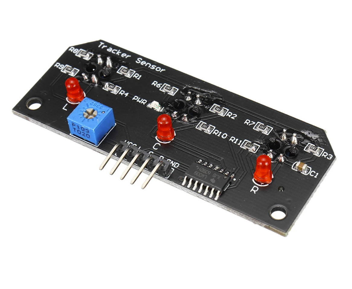
There is a 5-pin header on the assembly. The GND pin is connected to the system ground and the Vcc pin is connected to 5V. The L (Left), C (Center) and R (Right) pins are outputs that should connect to digital inputs on the microcontroller.
Module Connections:
1 x 5 Male Header
- VCC – Connect to 5V.
- L – Left Channel Detector. Connect to any digital input pin on a microcontroller.
- C – Center Channel Detector. Connect to any digital input pin on a microcontroller.
- R– Right Channel Detector. Connect to any digital input pin on a microcontroller.
- GND – Connect to system ground. This ground needs to be in common with the microcontroller.

