Programmable board WiFi Mega 2560 Compatible with Arduino
10.50 د.ك
These new boards have two processors on them
In stock
Description
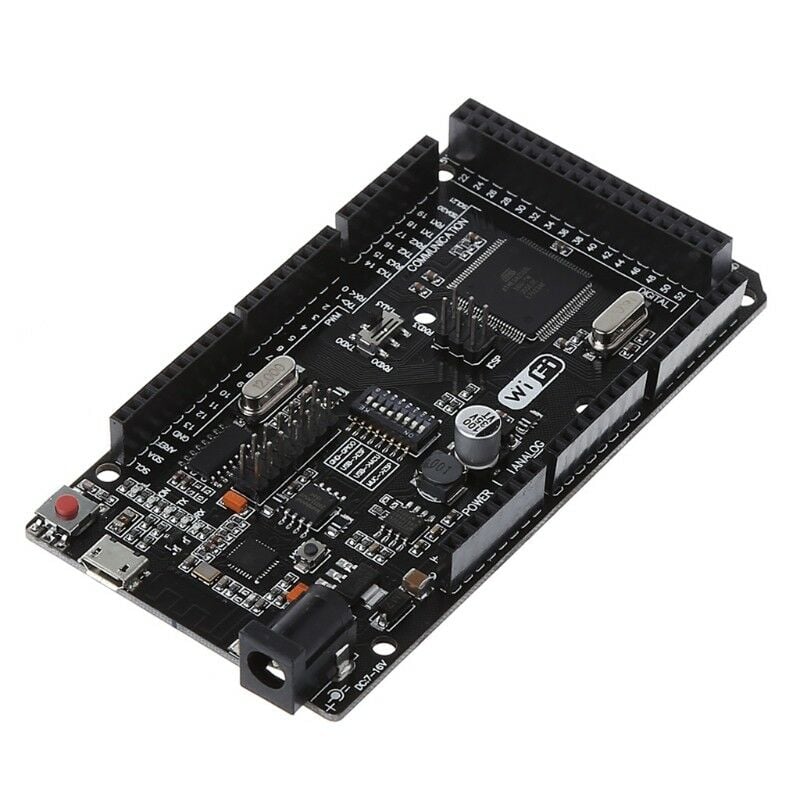
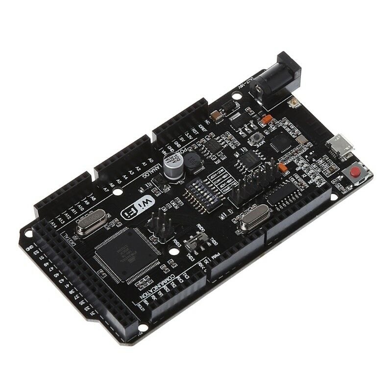
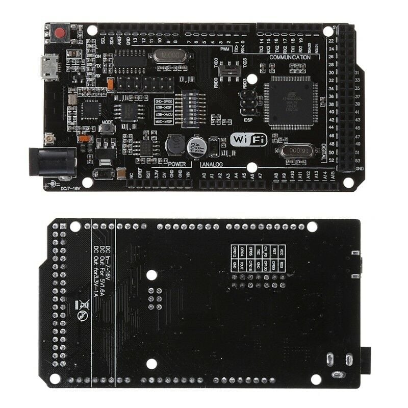
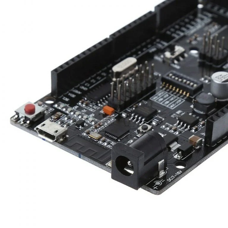
- Microcontroller: Atmega2560
- WiFi module: Esp8266
- Working Voltage: 5V
- Input Voltage (recommended): 7-12V
- Input Voltage (limit): 6-20V
- Digital I / O Pins: 54 (of which 15 are PWM output)
- Analog Input Pins: 16
- Current per I / O: 40 mA
- Current for 3.3V Output: 50 mA
- Flash Memory: 256 KB (Atmega2560) 8 KB of which is used by bootloader
- Flash Memory: 32 MB (Esp8266)
- SRAM: 8 KB (ATmega2560)
- EEPROM: 4 KB (ATmega2560)
- Clock Speed: 16 MHz
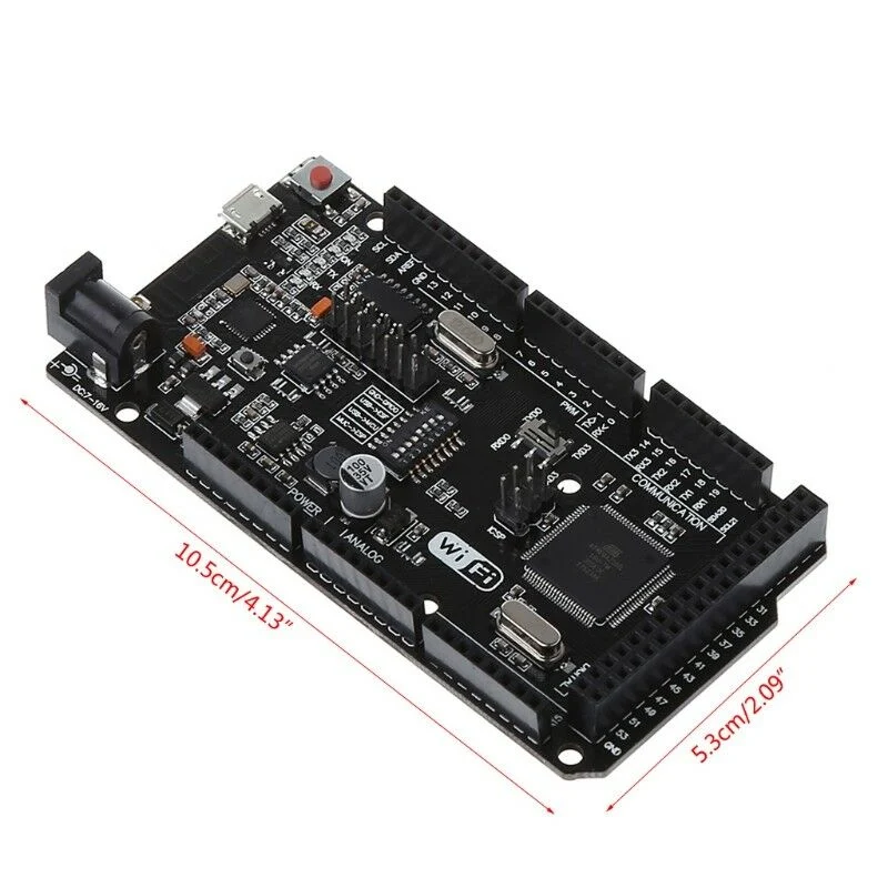
- Length: 101.6 mm
- Width: 53.4 mm
These new boards have two processors on them; both the traditional ATMEGA chips as well as the ESP8266 WiFi chips. This allows
them to act as co-processors to each other and provide WiFi functionality to your projects. As they are two separate processors, you
must upload code to both processors for them to function. In the source code, they will be able to communicate to each other
through Serial.read() and Serial.write() commands. You can set this by configuring the dip switches as per the table
below, so that the USB/programmer can communicate between both processors individually. Once you have finished programming,
configure the dip switches so both of the processors can communicate with each other to send messages back and forth. You will
find there is 8 dip switches on the board, labelled 1-8. You will need the following configuration:
When you want to … Dip Pins N.C.
1 2 3 4 5 6 7 8
… Program the Arduino OFF OFF ON ON OFF OFF OFF X
… Program the ESP8266 OFF OFF OFF OFF ON ON ON X
… Communicate between Computer serial and
ESP8266 OFF OFF OFF OFF ON ON OFF X
… Connect the ESP8266 Serial to the Arduino
Serial ON ON OFF OFF OFF OFF OFF X
Serial Selector: In addition to this, the XC4421 ATMEGA board has an additional slide switch which will configure whether to use
Serial0 or Serial3 for communication to the ESP8266. This is handy when you want to configure back and forth communication
between the PC, Arduino, and ESP all at once.
Please note, when programming the ESP8266, you must manually press reset on the board to restart the ESP8266 and enable it to
receive the programming instructions. Do this when it begins to say “uploading” on the arduino IDE. This manual assumes you have
configured the IDE to program ESP chips, such as mentioned in the XC3802 Manual.
For example:
When programming the Arduino Code, you must have switches 3 and 4 ON, and the others are off.
Then when you want to upload the ESP8266 Code, you can switch 5,6, and 7 ON, and all the others are switched off.
You can check with the serial monitor for the ESP8266 code, by turning switch 7 OFF (as a failsafe against reprogramming)
Finally, when both codes are uploaded, you switch all switches off and turn on switches 1 and 2.
This will enable your Arduino code to communicate to the ESP8266, and visa-versa, through the use of Serial.write()
and Serial.read() commands, at whichever baud-rate that you define in code. Test each bit of code against the serial
monitor to ensure that the flow is correct, and use the provided example code as a basis for your programming.
Document 3