Raspberry Pi Pico W
9.95 د.ك
Raspberry Pi Pico W brings WiFi + BLE (coming soon) wireless networking
In stock
Description
The Raspberry Pi foundation changed single-board computing when they released the Raspberry Pi computer, now they’re ready to do the same for microcontrollers with the release of the brand new Raspberry Pi Pico W. This low-cost microcontroller board features their powerful new chip, the RP2040, and all the fixin’s to get started with IoT embedded electronics projects at a stress-free price.
Raspberry Pi Pico W brings WiFi + BLE (coming soon) wireless networking to the Pico platform while retaining complete pin compatibility with its older sibling.
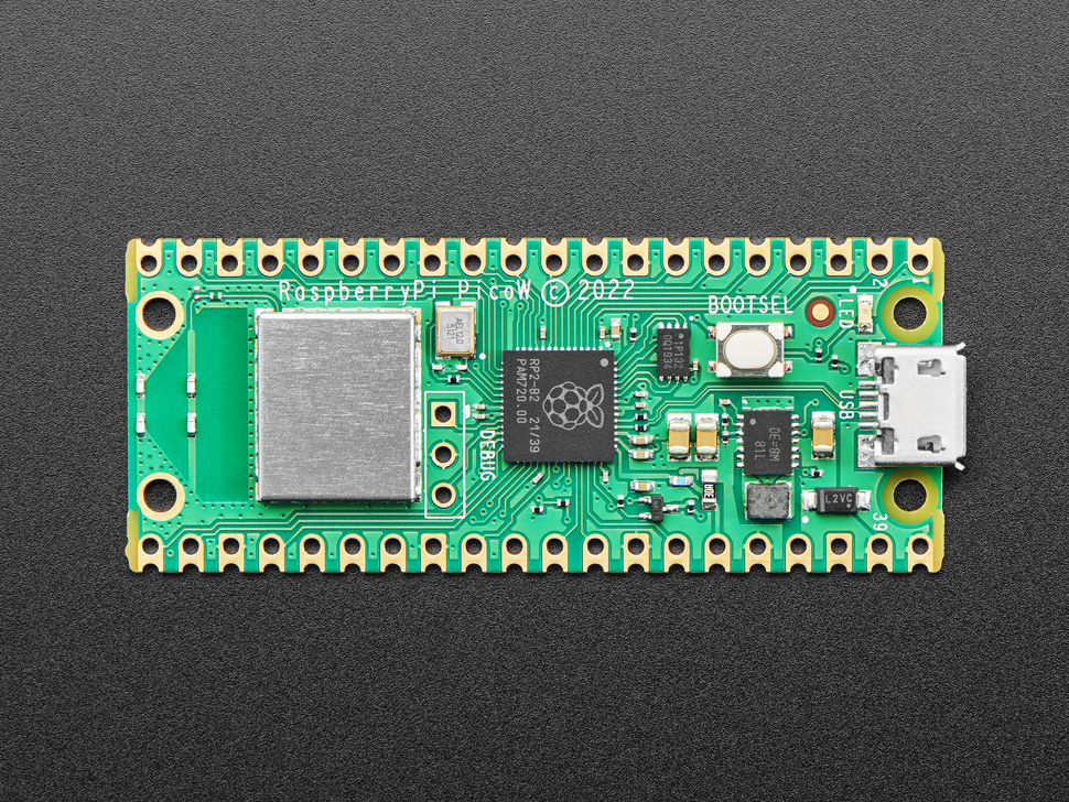
Raspberry Pi Pico W is just like the classic Pico but adds on-board single-band 2.4GHz wireless interfaces (802.11n) using the Infineon CYW43439 while retaining the Pico form factor. The on-board 2.4GHz wireless interface has the following features:
- Wireless (802.11n), Single-band (2.4 GHz) WiFi with WPA3 and Soft Access Point supporting up to 4 clients
- Bluetooth Low Energy – note this isn’t supported in software yet, its just a hardware capability.
- The wireless interface is connected via SPI to the RP2040 microcontroller and has a micropython driver for wireless capability
Due to pin limitations (the Pico brings out all the GPIO) some of the wireless interface pins are shared with the exposed pads:
- The SPI CLK is shared with VSYS monitor, so only when there isn’t an SPI transaction in progress can VSYS be read via the ADC.
- The Infineon CYW43439 SPI DIN/DOUT and IRQ all share one pin on the RP2040. Only when an SPI transaction isn’t in progress is it suitable to check for IRQs.
- The interface typically runs at 33MHz.
For best wireless performance, the antenna should be in free space. For instance, putting metal under or close by the antenna can reduce its performance both in terms of gain and bandwidth. Adding grounded metal to the sides of the antenna can improve the antenna’s bandwidth.
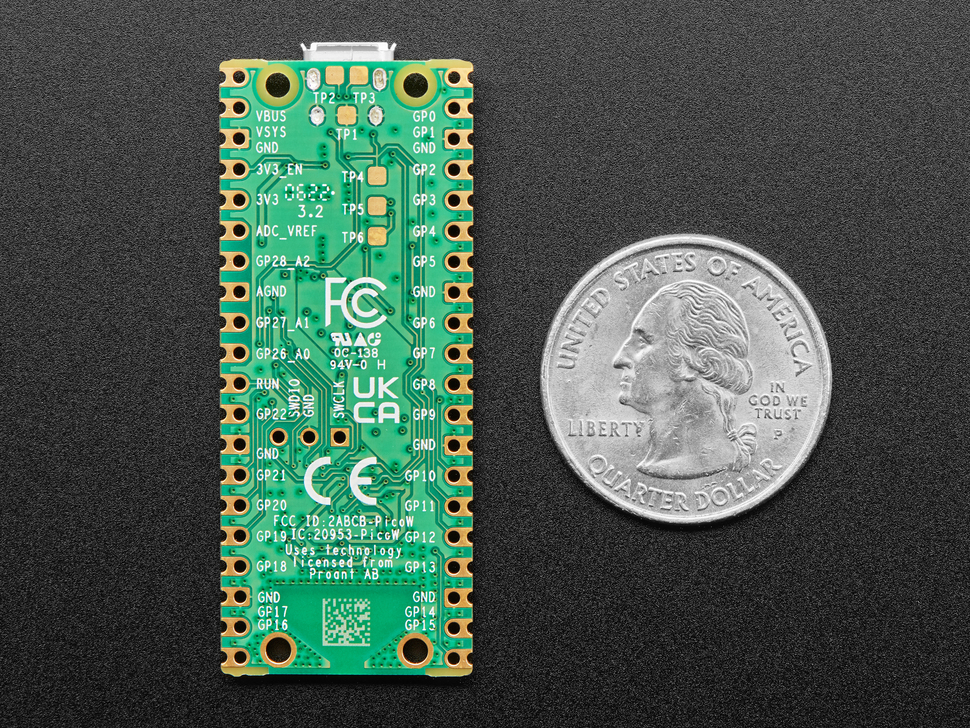
The Pico W is 51mm × 21mm × 1mm and can have headers soldered in for use in a breadboard or perfboard, or can be soldered directly onto a PCB with the castellated pads. There’s 20 pads on each side, with groups of general purpose input-and-output (GPIO) pins interleaved with plenty of ground pins. All of the GPIO pins are 3.3V logic, and are not 5V-safe so stick to 3V! You get a total of 25 GPIO pins, 3 of those can be analog inputs (the chip has 4 ADC but one is not broken out). There are no true analog output (DAC) pins.
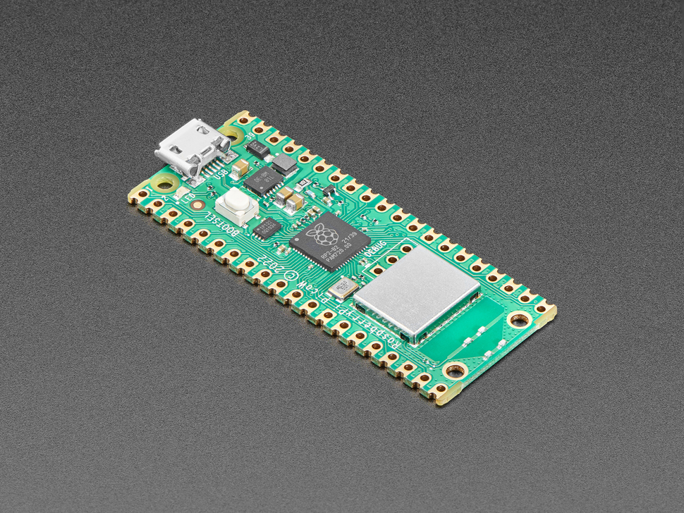
On the slim green board is minimal circuitry to get you going: A 5V to 3.3V power supply converter, single green LED connected through on the wireless module, boot select button, RP2040 chip with dual-core Cortex M0, Wireless chipset with antenna, 2 MegaBytes of QSPI flash storage, and crystal.
Inside the RP2040 is a ‘permanent ROM’ USB UF2 bootloader. What that means is when you want to program new firmware, you can hold down the BOOTSEL button while plugging it into USB (or pulling down the RUN/Reset pin to ground) and it will appear as a USB disk drive you can drag the firmware onto. Folks who have been using Adafruit products will find this very familiar – we use the technique all our native-USB boards. Just note you don’t double-click reset, instead hold down BOOTSEL during boot to enter the bootloader!
The RP2040 is a powerful chip, which has the clock speed of our M4 (SAMD51), and two cores that are equivalent to our M0 (SAMD21). Since it is an M0 chip, it does not have a floating point unit, or DSP hardware support – so if you’re doing something with heavy floating point math, it will be done in software and thus not as fast as an M4. For many other computational tasks, you’ll get close-to-M4 speeds!
For peripherals, there are two I2C controllers, two SPI controllers, and two UARTs that are multiplexed across the GPIO – check the pinout for what pins can be set to which. There are 16 PWM channels, each pin has a channel it can be set to (ditto on the pinout).
You’ll note there’s no I2S peripheral, or SDIO, or camera, what’s up with that? Well instead of having specific hardware support for serial-data-like peripherals like these, the RP2040 comes with the PIO state machine system which is a unique and powerful way to create custom hardware logic and data processing blocks that run on their own without taking up a CPU. For example, NeoPixels – often we bitbang the timing-specific protocol for these LEDs. For the RP2040, we instead use a PIO object that reads in the data buffer and clocks out the right bitstream with perfect accuracy. Same with I2S audio in or out, LED matrix displays, 8-bit or SPI based TFTs, even VGA! In MicroPython and CircuitPython you can create PIO control commands to script the peripheral and load it in at runtime. There are 2 PIO peripherals with 4 state machines each.
There is great C/C++ support, an official MicroPython port, and a CircuitPython port! and it has support with most of our drivers, displays, sensors, and more, supported out of the box so you can follow along with our CircuitPython projects and tutorials.
At the time of launch, only MicroPython has WiFi support.
While the RP2040 has lots of onboard RAM (264KB), it does not have built-in FLASH memory. Instead, that is provided by the external QSPI flash chip. On this board, there is 2MB, which is shared between the program it’s running and any file storage used by MicroPython or CircuitPython. When using C/C++ you get the whole flash memory, if using Python you will have about 1 MB remaining for code, files, images, fonts, etc.
RP2040 Chip features:
- Dual ARM Cortex-M0+ @ 133MHz
- 264kB on-chip SRAM in six independent banks
- Support for up to 16MB of off-chip Flash memory via dedicated QSPI bus
- DMA controller
- Fully-connected AHB crossbar
- Interpolator and integer divider peripherals
- On-chip programmable LDO to generate core voltage
- 2 on-chip PLLs to generate USB and core clocks
- 30 GPIO pins, 4 of which can be used as analog inputs
- Peripherals
- 2 UARTs
- 2 SPI controllers
- 2 I2C controllers
- 16 PWM channels
- USB 1.1 controller and PHY, with host and device support
- 8 PIO state machines
Related products
-
Raspberry Pi 4 only 15.3W USB-C Power Supply UK
8.00 د.ك Add to cart -
Raspberry Pi 3 Model B+
22.00 د.ك Read more -
HD USB 2.0 Webcamera camera
7.95 د.ك Add to cart -
Sale!
Raspberry Pi 3 Kit + Preinstalled SD Card with Raspbian
Original price was: 37.75 د.ك.34.75 د.كCurrent price is: 34.75 د.ك. Read more