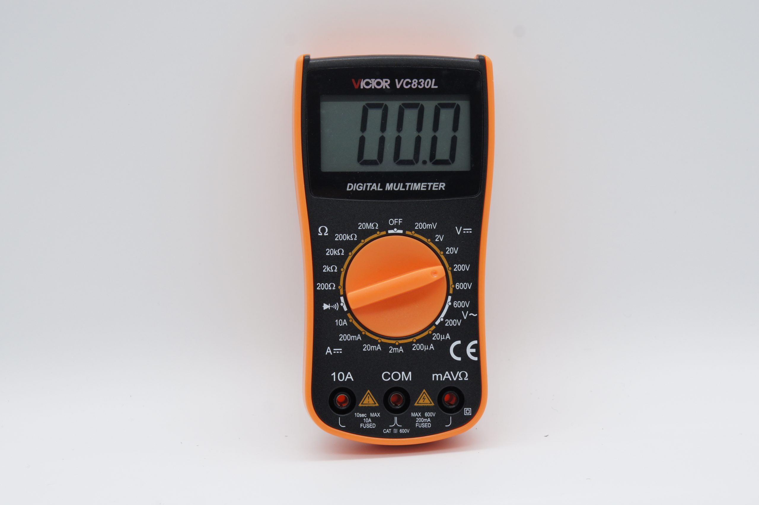
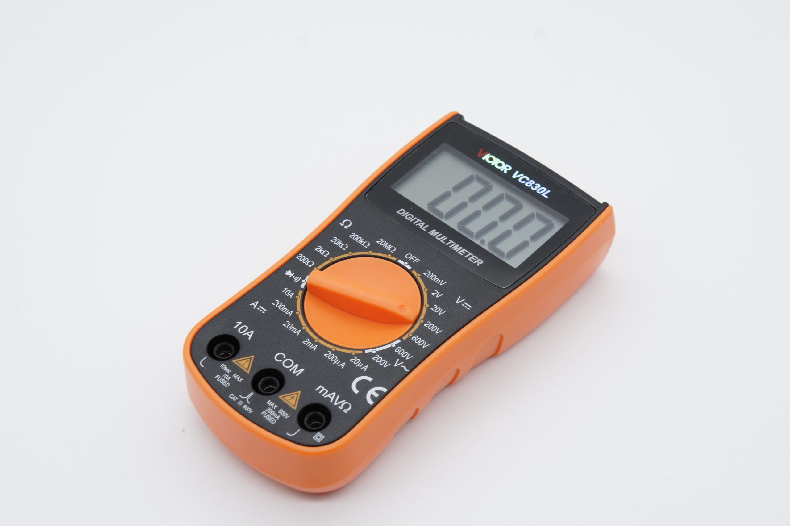
Multimeter Victor VC830L
4.00 د.ك
The instrument is a pocket digital multimeter, which is used to measure DCV, ACV, and DCA, resistance, diode and continuity test.
In stock
Description
DIGITAL MULTIMETER OPERATION MANUAL
- General
The instrument is a pocket digital multimeter, which is used to measure DCV, ACV, and DCA, resistance, diode and continuity test. It is an ideal tool for labs, household and wireless enthusiasts.
- Safety Notes
- Do not input a limit value over the range when measuring.
- When measuring voltage higher than 36V DCV, 25V ACV, check the connection and insulation of the test leads to avoid electric shock.
- Keep the test leads away from the testing point when converting function and range.
- Don’t add voltage to the input terminal when measuring resistance.
- Specification
- General Features
1-1. Displaying: 22mm digit height LCD display.
1-2. Max. Indication: 1999 (31/2) auto polarity indication.
1-3. Sampling rate: approx. 3 times/ sec
1-4. Over Range Indication: MSD displays “1”
1-5. Low Battery Indication: ” ” symbol displays.
1-6. Operation Environment: (0~40)℃, relative humidity <80% .
1-7. Power: 9V battery (NEDA1604/6F22 or equivalent)
1-8. Measurement: 145×85×30mm (Length×Width×Height)
1-9. Weight: Approx. 170g (including a 9V battery)
1-10. Accessories: Operation Manual, Product Certificate, Packing box, Test leads and a 9V battery.
- Technical Features
Accuracy: ± (a%×reading+d)
Surrounding: (23±5)℃, relative humidity<75%. One year warranty since the date of manufacture.
- DCV
| Range | Accuracy | Resolution |
| 200mV | ±(0.5%+4) | 100uV |
| 2V | 1mV | |
| 20V | 10mV | |
| 200V | 100mV | |
| 600V | ±(1.0%+5) | 1V |
Input impedance: 1MΩfor all ranges.
- ACV
| Range | Accuracy | Resolution |
| 200V | ±(1.2%+10) | 100mV |
| 600V | 1V |
Input impedance: 1MΩ.
Frequency Response: (40~200)Hz
- DCA
| Range | Accuracy | Resolution |
| 20uA | ±(1.5%+3)
|
0.01uA |
| 200uA | 0.1uA | |
| 2mA | 1uA | |
| 20mA | 10uA | |
| 200mA | 100uA | |
| 10A | ±(2.0%+5) | 10mA |
Max. Input current: 10A (no more than 6 seconds)
Overload Protection: 0.2A/250V; 10A/250V fuse.
- Resistance
| Range | Accuracy | Resolution |
| 200Ω | ±(0.8%+5) | 0.1Ω |
| 2kΩ |
±(0.8%+3) |
1Ω |
| 20kΩ | 10Ω | |
| 200kΩ | 100Ω | |
| 20MΩ | ±(1.0%+15) | 10kΩ |
Overload Protection: 250V DC/AC peak value
Note: At range 200Ω, first short-circuit the meter pens to measure the wire resistance. Then subtract it from the real measurement.
- Diode and continuity test
| Range | Display | Testing Condition |
| Forward voltage drop of diode | Forward DCA is approx. 1mA,
Backward voltage is apporx.3V |
|
| Buzzer makes a long sound while resistance is less than (70±20)Ω | Open voltage is approx.3V |
Overload Protection: 250V DC/AC peak value
- DC Voltage Measurement
- Apply the black test lead to “COM” terminal and the red test lead to “V/Ω” terminal.
- Set the knob to a proper DCV range, and connect the test leads crossly to the electric circuit under test. LCD displays polarity and voltage under test connected by the red test lead.
Note:
- Firstly, the knob should be set to the highest range if users have no idea about the range of voltage under test. Then select the proper range based on display value.
- If MSD displays “1″, it means the meter is over range. Please set the knob to a higher range.
- Do not attempt to input voltage over 600V. Otherwise, it may damage the circuit of the meter.
- Avoid touching high voltage circuit when measuring it.
- AC Voltage Measurement
- Apply the black test lead to “COM” terminal and the red test lead to “V/Ω” terminal.
- Set the knob to a proper ACV range, and connect the test leads crossly to the electric circuit under test.
Note:
- Firstly, the knob should be set to the highest range if users have no idea about the range of voltage under test. Then select the proper range based on display value.
- If MSD displays “1″, it means the meter is over range. Please set the knob to a higher range.
- Do not attempt to input voltage over 600Vrms. Otherwise, it may damage the circuit of the meter.
- Avoid touching high voltage circuit when measuring it.
- DC Current Measurement
- Apply the black test lead to “COM” terminal and the red test lead to “V/Ω” terminal (max. 200mA), or put the red test lead to “10A” terminal (max. 10A).
- Set the knob to a proper DCA range, and connect the test leads in series to the electric circuit under test. LCD displays polarity and current value under test connected by the red test lead.
Note:
- Firstly, the knob should be set to the highest range if users have no idea about the range of voltage under test. Then select the proper range based on display value.
- If MSD displays “1″, it means the meter is over range. Please set the knob to a higher range.
- The max input current is 200mA or 10A (depends on the insert position of the red meter pen). Excessive current will melt the fuse. When measuring, if the meter has no reading display, please check relevant fuse.
- Resistance Measurement
- Apply the black test lead to “COM” terminal and the red test lead to “V/Ω” terminal.
- Set the knob to a proper resistance range, and connect the leads crossly to the resistance under test.
Note:
- The LCD displays “1” when the resistance is over the selected range. The knob should be adjusted to a higher range. When resistance under test is over 1MΩ, the reading shall be stable in a few seconds, which is a normal status when measuring high resistance.
- When the input terminal is in open circuit, it displays overload.
- When measuring in line resistor, be sure that the power is off and all capacitors are released completely.
- It is absolutely forbidden to input voltage at the range of resistance, though the meter has voltage protection function at this range.
- Diode Test
- Apply the black test lead to “COM” terminal and the red lead to “V/Ω” terminal (the polarity of red lead is “+”)
- Set the knob to“ ”range, connect test leads to the diode under test. The red test lead connects to diode positive polarity and the reading is the approx. value of diode forward voltage drop.
- Continuity Test
Set the knob to“ ”range, apply test leads to the two points of tested circuit. If the inner buzzer sounds, the resistance is less than (70±20) Ω.
- Maintenance
This is a precise meter; please don’t try to modify the circuit.
Note:
- Do not input voltage over DC600V or AC 600Vrms.
- Do not measure voltage on range Ω.
- Do not use this meter for measurement if the battery is not correctly placed or the back case is not properly screwed.
- Remove the test leads from the testing points and turn off the meter before replacing battery or fuse.
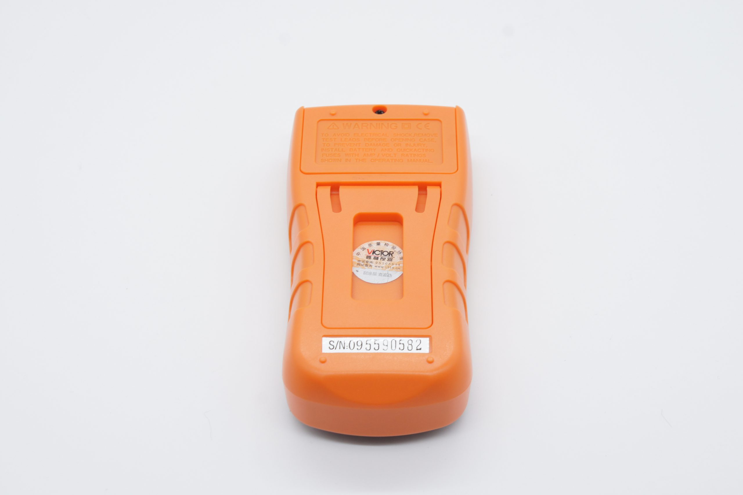
Battery Replacement
Note: Pay attention to the battery status.
Please replace the battery when LCD displays “ ” .
Steps:
- Unscrew the battery cover.
- Take out the 9V battery and replace it with a new one.
- Install and screw the battery cover.
Fuse Replacement (This operation could only be processed in power off status.)
- Unscrew the battery cover.
- Take out the battery and open the back cover.
- Please use fuse of the same specification.
Related products
-
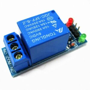
relay module
1.25 د.ك Add to cart -
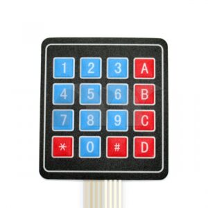
4 * 4 matrix keyboard
1.00 د.ك Add to cart -
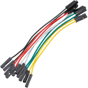
jumper wires 10 wires each set
Price range: 0.40 د.ك through 1.00 د.ك Select options This product has multiple variants. The options may be chosen on the product page -
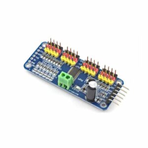
PCA9685 16-channel 12-bit PWM driver
6.00 د.ك Add to cart